
Coordinates Boat Game: Exploring Coordinate and Random Process
Loading the math board and drawing, please wait…
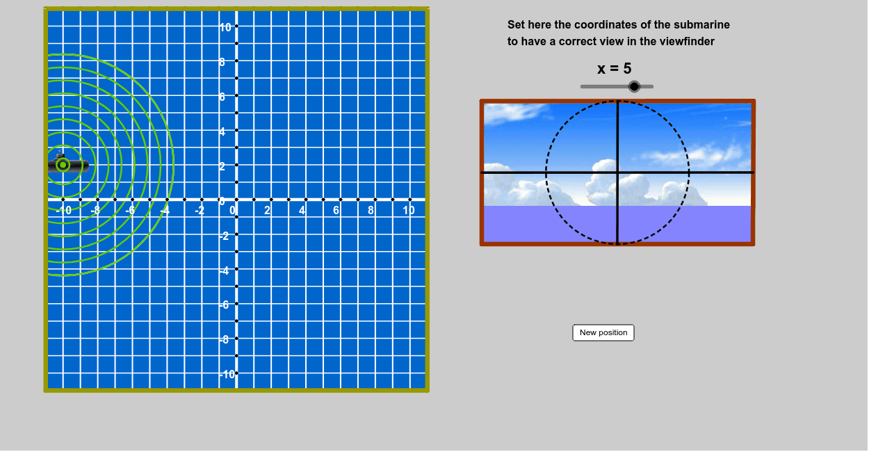
This example demonstrates how to control the position of a boat in a coordinate system using sliders, showcasing the application of random processes in geometric figures. Key mathematical concepts include coordinate geometry, random processes, and geometric construction. Construction involves using GeoGebra commands such as Random, Circle, Ray, etc. Suitable for middle school or high school students to learn basic concepts of coordinate geometry and random processes.
GeoGebra Commands & Parameters
Random(-10, 10) → bbRandom(-10, 10) → aaRandom(-10, 10) → ccRandom(4, 15) → rrCircle(A, (1.5 * v - 1) * rr) → c'Ray(A, (0, 0)) → aOrthogonalLine(A, a) → bIntersect(c', b) → B, CIntersect(c', a) → D, TCircumcircleArc(B, D, C) → dMidpoint(C, D) → EMidpoint(B, D) → F_2Ray(A', E) → eRay(A', F_2) → fIntersect(d, e) → G,Intersect(d, f) → H,CircumcircleArc(G, D, H) → gCircle(I, 1) → hSequence(Text[If[s < 10, " ", ""] + (s), (21.6 + 2 * Mod[s - 1, 3], 7.75 - 2 * Div[s - 1, 3])], s, 1, 12) → liste3Circle(J, 1) → kSequence(Text[If[s ≟ 1, " ", If[s < 5, " ", ""]] + (30 * (s - 1)) + "º", (21.25 + 2 * Mod[s - 1, 3], -6.25 - 2 * Div[s - 1, 3])], s, 1, 12) → liste4If(yB > -5, 5*°, (((xB - 3 * yB) / 2 - 19 - 1) * 30)°) → angIf(ang ≟ α ∧ dist ≟ rr, true, false) → razSegment(O, N) → mCircle(A, (2 * v - 1) * rr - n) → pSequence(Circle[A, (1.5 * v - 1) * rr - i], i, 0, n, n / 10) → liste5Polygon(P, Q, R, S) → poly1, p_1, q, r_1, sCircle((0, 0), If[2 * v * rr > 12, 0, 2 * v * rr]) → cMidpoint(K, L) → UMidpoint(U, L) → VMidpoint(U, V) → WMidpoint(V, L) → ZSegment(K, C_1) → lLine(A, l) → iSegment(A, U) → tIntersect(c, t) → A_1, B_1Segment(U, A_1) → a_1Rotate(C_1, 6 * v, U) → L'Segment(U, L') → b_1Mod(v * 100, 2) → abSegment(O, D_1) → jCircle(O, C_1) → g_1Point(g_1) → E_1Segment(O, E_1) → h_1Circle(F_1, 6.5 - abs(r / 4.5)) → q_1Line(F_1, l) → i_1Intersect(q_1, i_1) → G_1, H_1Line(J_1, r_1) → j_1Point(j_1) → N_1Line(N_1, l) → l_1Line(J_1, l) → m_1Point(m_1) → O_1Point(l_1) → P_1Intersect(l_1, r_1) → M_1Polygon(M_1, N_1, J_1, F) → poly2, m_2, n_1, j_2, f_2Point(l_1) → Q_1Point(m_1) → R_1Polygon(P_1, Q_1, R_1, O_1) → poly3, p_2, q_2, r_2, o_1Point(j_1) → S_1Polygon(S_1, T_1, O_1, J_1) → poly4, s_1, t_1, o_2, j_3Midpoint(s_1) → V_1Midpoint(o_2) → W_1Midpoint(S_1, J_1) → Z_1Midpoint(t_1) → A_2Segment(V_1, W_1) → a_2Segment(Z_1, A_2) → b_2Intersect(b_2, a_2) → B_2Circle(B_2, V_1) → c_2Sequence((x(O) + i, y(D_1)), i, -11, 11, 1) → liste1Sequence((x(N) + i, y(N)), i, -11, 11, 1) → liste6Sequence((x(C_1), y(C_1) + i), i, -11, 11, 1) → liste7Sequence((x(E_1), y(E_1) + i), i, -11, 11, 1) → liste8Ray(M_1, T_1) → c_1Sequence(Segment[Element[liste8, i], Element[liste7, i]], i, 0, 22) → liste10Sequence((x(D_1) + i, 0), i, -11, 11) → liste2Sequence(Segment[Element[liste1, i], Element[liste6, i]], i, 0, 22) → liste9Line(S, P) → d_1Line(J_1, S_1) → e_1Line(Q_1, e_1) → f_1Intersect(d_1, s) → MIntersect(d_1, f_1) → C_2Line(R, d_1) → k_1Intersect(e_1, k_1) → D_2Polygon(S, C_2, Q_1, S_1, D_2, R) → poly5, s_2, c_3, q_3, s_3, d_2, r_3Point(d_1) → E_2Line(E_2, p_1) → e_2Intersect(k_1, e_2) → G_2Polygon(E_2, P, Q, G_2) → poly6, e_3, p_3, q_4, g_2Sequence(O + (i, 0), i, -10, 10) → liste11Sequence(O + (0, i), i, -10, 10) → liste12Sequence(i, i, -10, 10) → liste13Sequence(Text[Element[liste13, i], (x(Element[liste11, i] - 0.42), y(Element[liste11, i] - 0.85))], i, 1, Length[liste13], 2) → liste14Sequence(Text[Element[liste13, i], (x(Element[liste12, i] - 1), y(Element[liste12, i] - 0.31))], i, 1, Length[liste13], 2) → liste15
AI Drawing Prompt Reference
In a coordinate system, control the position of a boat using a slider to demonstrate the application of random processes in geometric figures. First, draw a random circle and two rays, then find the intersection points of the circle with the rays and draw arcs and line segments. Next, use the center, intersection points, and midpoints of line segments to draw new circles and rays, and find their intersection points. Finally, draw a series of circles and text based on the slider values, and connect key points to form polygons and line segments to complete the construction of the entire figure.
The prompt above was compiled from the original drawing commands and is for reference only.