
斯里扬特拉的分步几何构造
几何画板及绘图内容加载中,请稍等……
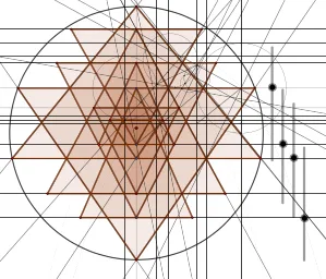
该范例演示如何在平面上用一组严格的几何作图步骤构造“斯里扬特拉”(Sri-Yantra)图案的关键对称结构。核心数学概念包括:线段与射线/直线的构造、圆与弧(含半圆)生成、对称与镜像、角平分线、线段中点、垂线/正交线、交点确定新顶点,以及由这些点拼接出多重线框多边形网络。作图要点:利用 GeoGebra 的 Intersect 求交点;用 Point、Line、Ray、Segment、Midpoint 生成与定位基础几何要素;通过 Semicircle、Circle、Parabola 提供曲线构型的中间约束(例如以圆/弧确定层次边界);借助 OrthogonalLine 构造垂直关系;用 Mirror、LineBisector、AngularBisector 实现对称与角平分;最终采用 Polygon 组织成目标图案的多边形/线网结构。适合用于中学竞赛几何、数学兴趣小组的几何作图课,以及函数与几何结合的可视化教学或学生自主探究(强调“从基本作图命令到复杂对称图案”的建模过程)。
GeoGebra 命令及参数
Intersect(xAxis, yAxis) → APoint(yAxis) → BSemicircle(B, A) → c_6Semicircle(A, B) → d_3Line(B, A) → fOrthogonalLine(C, f) → gOrthogonalLine(E, f) → hIntersect(c_6, g, 1) → GIntersect(c_6, h, 1) → HLine(B, H) → iLine(A, G) → jIntersect(d_3, g, 1) → ILine(A, I) → kIntersect(d_3, h, 1) → JLine(B, J) → lIntersect(g, i) → KOrthogonalLine(D, f) → qIntersect(h, j) → QIntersect(f, yAxis) → Q_1Ray(F, K) → mIntersect(h, m) → LRay(C, L) → nIntersect(j, n) → MOrthogonalLine(M, f) → pIntersect(f, p) → NIntersect(q, n) → ORay(N, O) → rSegment(D, K) → sIntersect(q, m) → PSegment(P, C) → tIntersect(s, t) → RRay(B, R) → a_7Intersect(g, a_7) → SIntersect(g, r) → TLine(D, a_7) → f_1Line(Q, r) → g_1Intersect(f_1, g) → UIntersect(g_1, g) → VMidpoint(D, C) → WOrthogonalLine(Q, g) → b_7Intersect(g, b_7) → ZMidpoint(Z, Q) → A_1OrthogonalLine(A_1, b_7) → eOrthogonalLine(W, f) → h_1OrthogonalLine(U, g) → i_1OrthogonalLine(V, g) → j_1Midpoint(U, T) → B_1Midpoint(S, V) → C_1OrthogonalLine(B_1, g) → k_1OrthogonalLine(C_1, g) → l_1Intersect(k_1, h_1) → F_1Intersect(l_1, e) → G_1Segment(G_1, V) → m_1Segment(U, F_1) → n_1Midpoint(U, F_1) → H_1Midpoint(G_1, V) → I_1OrthogonalLine(I_1, m_1) → p_1OrthogonalLine(H_1, n_1) → q_1Intersect(k_1, q_1) → J_1Intersect(p_1, l_1) → K_1Intersect(p_1, j_1) → L_1Intersect(i_1, q_1) → M_1Intersect(e, j_1) → E_1Circle(V, L_1) → c_1Intersect(c_1, j_1) → D_1, N_1Intersect(g, f_1) → O_1Circle(U, M_1) → d_1Intersect(d_1, i_1) → P_1, R_1OrthogonalLine(R_1, i_1) → r_1OrthogonalLine(N_1, j_1) → s_1Parabola(K_1, s_1) → e_1Parabola(J_1, r_1) → t_1Intersect(t_1, e_1) → S_1, T_1, ,OrthogonalLine(S_1, g) → a_1Intersect(a_1, g) → U_1OrthogonalLine(T_1, h_1) → b_1Intersect(k_1, r_1) → V_1Intersect(k_1, s_1) → W_1Line(V_1, K_1) → f_2Line(W_1, f_2) → g_2Intersect(l_1, g_2) → Z_1Circle(K_1, Z_1) → c_2Intersect(c_2, l_1) → A_2, B_2Segment(J_1, Z_1) → h_2Line(J_1, B_2) → i_2Intersect(l_1, r_1) → C_2Circle(J_1, Z_1, C_2) → d_2Intersect(d_2, i_2) → D_2, E_2Intersect(c_2, d_2) → F_2, G_2, ,Line(Z_1, G_2) → j_2Intersect(j_2, i_2) → H_2Semicircle(K_1, H_2) → e_2Semicircle(H_2, K_1) → k_2Intersect(c_2, k_2) → I_2, M_3, ,Circle(J_1, E_2, I_2) → p_2Ray(D, U_1) → l_2Intersect(i, l_2) → J_2OrthogonalLine(J_2, f) → m_2Intersect(m_2, f) → K_2Segment(K_2, P) → n_2Intersect(l_2, a_7) → L_2OrthogonalLine(L_2, f) → q_2Intersect(j_2, r) → M_2Intersect(r, q_2) → N_2Ray(Q, N_2) → r_2Intersect(l_2, r_2) → O_2Intersect(r_2, f) → P_2OrthogonalLine(P_2, f) → s_2Intersect(i, s_2) → Q_2Intersect(s_2, l_2) → R_2OrthogonalLine(F, f) → t_2Line(P_2, Q) → a_2Intersect(p, a_2) → S_2Intersect(t_2, n) → T_2Intersect(j, t_2) → U_2Intersect(i, j) → V_2Intersect(m, m_2) → W_2Intersect(n, l_2) → Z_2OrthogonalLine(Z_2, f) → b_2Intersect(n_2, b_2) → A_3Mirror(T_2, f) → B_3Mirror(S_2, f) → C_3Mirror(W_2, f) → D_3Mirror(R_2, f) → E_3Mirror(A_3, f) → F_3Mirror(L_2, f) → G_3Mirror(N_2, f) → H_3Mirror(P, f) → P'Midpoint(D, Z_2) → I_3LineBisector(D, Z_2) → l_7Intersect(l_7, f) → J_3AngularBisector(b_2, l_2) → g_3, h_3Intersect(g_3, f) → K_3Segment(A_3, E) → i_3Segment(E, H) → j_3Segment(H, B) → k_3Semicircle(B, A) → c_3Segment(A, G) → l_3Segment(G, C) → m_3Segment(C, T_2) → n_3Segment(T_2, F) → p_3Segment(F, W_2) → q_3Segment(W_2, K_2) → r_3Segment(K_2, P) → s_3Segment(P, D) → t_3Segment(D, R_2) → a_3Segment(R_2, P_2) → b_3Segment(P_2, S_2) → f_4Segment(S_2, N) → g_4Segment(N, N_2) → h_4Segment(N_2, H_3) → i_4Segment(H_3, N) → j_4Segment(N, C_3) → k_4Segment(C_3, P_2) → l_4Segment(P_2, E_3) → m_4Segment(E_3, D) → n_4Segment(D, P') → p_4Segment(P', K_2) → q_4Segment(K_2, D_3) → r_4Segment(D_3, F) → s_4Segment(F, B_3) → t_4Segment(B_3, C) → a_4Segment(C, I) → b_4Segment(I, A) → c_4Semicircle(A, B) → d_4Segment(B, J) → e_4Segment(J, E) → f_5Segment(E, F_3) → g_5Segment(F_3, A_3) → h_5Polygon(F_3, E, A_3) → t2, i_5, j_5, e_5Polygon(K_2, P', P) → t3, p_5, k_5, p'Polygon(H_3, N_2, N) → t4, n_5, l_5, m_5Polygon(C, B_3, T_2) → t5, q_5, c_5, r_5Polygon(E_3, D, R_2) → t6, s_5, t_5, d_5Polygon(P_2, C_3, S_2) → t7, a_5, b_5, f_6Polygon(D_3, F, W_2) → t8, w_2, g_6, f_7Polygon(B, J, H) → t9, h_6, b_6, j_6Polygon(I, G, A) → t10, a_6, i_6, g_7Intersect(g_3, f) → L_3
AI 绘图提示语参考
请绘制一个对称的几何图形,包含两个圆弧和一条直线。圆弧的端点是直线的交点。直线与圆弧相交后,通过垂直线与圆弧的交点连接,形成新的点。然后用这些点连接成线段,并用垂直线与直线相交。最后,用这些线段和垂直线形成一个封闭的图形。图形应保持对称性,线条清晰。
以上提示语为根据原始绘图命令整理而来,仅供参考。