
八面体展开图
几何画板及绘图内容加载中,请稍等……
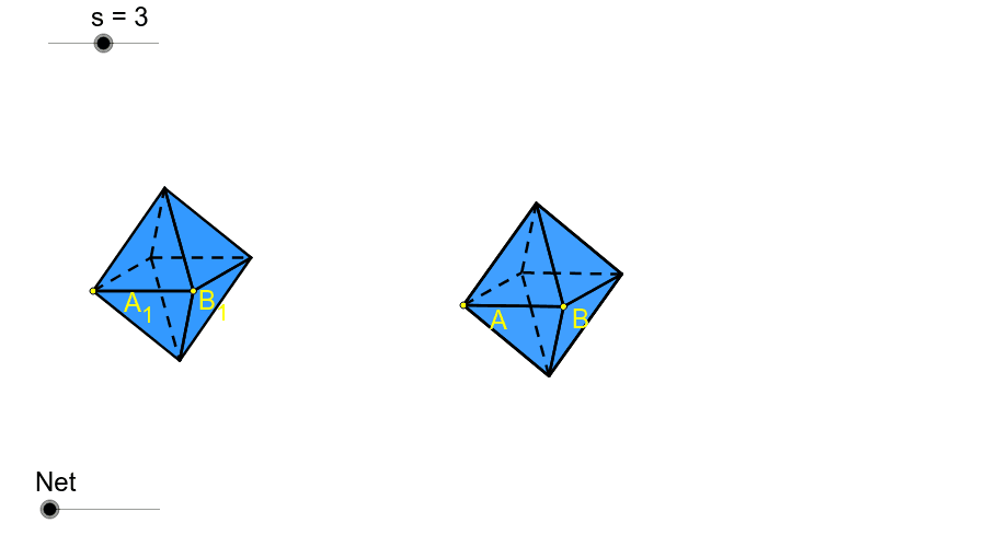
这个GeoGebra范例演示了八面体的展开图,并通过动画展示了其构造过程。核心数学概念包括立体几何和几何作图。使用了点、线段、圆、旋转、镜像等GeoGebra命令。适合初中及以上学生学习立体几何和几何作图。
GeoGebra 命令及参数
Point(Circle[A, s]) → BSegment(A, B) → aLine(A, B) → bCircle(B, 3.0 * s / 4.5) → cIntersect(c, b, 2.0) → CRotate(C, 30.0*°, B) → C'Line(C', b) → dSegment(B, C') → eLine(A, e) → fIntersect(d, f) → DSegment(A, C') → gSegment(D, B) → hIntersect(g, h) → EOrthogonalLine(E, a) → iRotate(i, 5.0*°, E) → i'Circle(E, s * sqrt(3.0) / 2.0) → kIntersect(k, i', 1.0) → FIntersect(k, i', 2.0) → GPolygon(D, C', 3.0) → poly1, j, d_1, c', HPolygon(D, H, 3.0) → poly2, l, d_2, h_1, IPolygon(I, H, 3.0) → poly3, m, i_1, h_2, JPolygon(H, C', 3.0) → poly4, n, h_3, c'_1, KPolygon(C', D, 3.0) → poly5, p, c'_2, d_3, LPolygon(C', L, 3.0) → poly6, q, c'_3, l_1, MPolygon(L, D, 3.0) → poly7, r, l_2, d_4, NPolygon(M, L, 3.0) → poly8, t, m_1, l_3, OPolygon(G, A, D) → poly9, d_5, g_1, a_1Mirror(D, d_5) → D'Vector(B, D') → uVector(A, I) → vVector(D', J) → wCircle(J, D', B) → c_1Translate(B, Vector[u * o]) → B'_1Center(c_1) → PRay(P, B'_1) → b_1Intersect(c_1, b_1, 1.0) → QTranslate(D', Vector[w * (o - 1.0)]) → D''Ray(P, D'') → e_1Intersect(c_1, e_1, 1.0) → RIf(o < 1.0, Q, If[o < 2.0, R, J]) → SSegment(I, A) → f_1LineBisector(f_1) → j_1Intersect(f, j_1) → TCircleArc(T, I, A) → k_1Translate(A, Vector[v * (o - 1.0)]) → A'_1Ray(T, A'_1) → n_1Intersect(k_1, n_1, 1.0) → UIf(o < 1.0, A, If[o < 2.0, U, I]) → VSegment(B, K) → p_1LineBisector(p_1) → q_1Intersect(q_1, c') → ZVector(G, H) → zVector(B, K) → u_1Translate(G, Vector[z * (o - 1.0)]) → G'LineBisector(G, H) → r_1Intersect(b, r_1) → WCircleArc(W, H, G) → s_1Ray(W, G') → t_1Intersect(s_1, t_1) → A_1,If(o < 1.0, G, If[o < 2.0, A_1, H]) → B_1Polygon(B_1, D, C') → poly10, c'_4, b_2, d_6Polygon(V, B_1, S) → poly11, s_2, v_1, b_3Polygon(V, D, B_1) → poly12, b_4, v_2, d_7LineBisector(K, B) → a_2LineBisector(A, B) → c_2OrthogonalLine(H, b) → e_2Intersect(b, c_2) → C_1Intersect(e_2, b) → D_1Vector(C_1, D_1) → w_1Translate(c_2, Vector[w_1 * (o - 1.0)]) → f_2Mirror(V, f_2) → V'If(o < 1.0, B, If[o < 2.0, V', K]) → E_1Polygon(B_1, E_1, C') → poly13, c'_5, b_5, e_3Polygon(B_1, D, C') → poly14, c'_6, b_6, d_8Midpoint(A, B) → F_1Vector(B, M) → z_1Vector(F, L) → u_2Polygon(C', B, F) → poly15, f_3, c'_7, b_7Mirror(C', B) → C''Vector(A, C'') → w_2Vector(A, N) → g_2Circle(C'', s / 5.0) → k_2Line(C', B) → i_2Intersect(k_2, i_2, 2.0) → G_1CircumcircleArc(A, G_1, O) → p_2Center(p_2) → H_1Translate(A, Vector[w_2 * (o - 2.0)]) → A'Ray(H_1, A') → j_2Intersect(p_2, j_2, 1.0) → I_1Vector(G_1, O) → z_2Translate(G_1, Vector[z_2 * (o - 3.0)]) → J_1Ray(H_1, J_1) → m_2Intersect(p_2, m_2, 1.0) → K_1If(o < 2.0, A, If[o < 3.0, I_1, If[o < 4.0, K_1, O]]) → L_1LineBisector(B, M) → n_2Translate(B, Vector[z_1 * (o - 3.0)]) → B'Segment(A, H_1) → q_2Segment(B, M) → r_2Intersect(n_2, r_2) → M_1Intersect(n_2, q_2) → N_1CircleArc(N_1, B, M) → t_2Ray(N_1, B') → a_3Intersect(t_2, a_3, 1.0) → O_1If(o < 3.0, B, If[o < 4.0, O_1, M]) → P_1LineBisector(F, L) → c_3Intersect(l_2, c_3) → Q_1CircleArc(Q_1, F, L) → g_3Translate(F, Vector[u_2 * (o - 3.0)]) → F'Ray(Q_1, F') → i_3Intersect(g_3, i_3, 1.0) → R_1If(o < 3.0, F, If[o < 4.0, R_1, L]) → S_1Polygon(S_1, P_1, L_1) → poly16, l_4, s_3, p_3Polygon(S_1, C', P_1) → poly17, p_4, s_4, c'_8Polygon(S_1, C', D) → poly18, d_9, s_5, c'_9Midpoint(A, B) → T_1OrthogonalLine(T_1, b) → j_3Intersect(b, e_2) → U_1Vector(T_1, U_1) → u_3Translate(j_3, Vector[u_3 * (o - 3.0)]) → k_3Mirror(P_1, k_3) → V_1If(o < 3.0, A, If[o < 4.0, V_1, N]) → W_1Polygon(W_1, S_1, D) → poly19, d_{10}, w_3, s_6Intersect(b_6, s_5) → Z_1Intersect(c'_5, s_5) → A_2Intersect(b_4, s_6) → B_2Intersect(v_1, s_6) → C_2Segment(C_2, A) → m_3Segment(C_2, D) → n_3Segment(V, D) → q_3Segment(C', A_2) → r_3Segment(D, A_2) → t_3Intersect(v_1, t_3) → D_2Segment(D_2, A_2) → a_4Segment(D_2, D) → c_4Intersect(s_3, c'_9) → E_2Segment(E_2, S_1) → e_4Intersect(v_1, c'_9) → F_2Segment(F_2, E_2) → f_4Segment(F_2, D) → g_4Segment(E_2, D) → h_4Intersect(b_3, c'_9) → G_2Segment(G_2, D) → i_4Segment(G_2, E_2) → j_4Point(Circle[H_2, s]) → I_2Segment(H_2, I_2) → k_4Line(H_2, I_2) → m_4Circle(I_2, 3.0 * s / 4.5) → q_4Intersect(q_4, m_4, 2.0) → J_2Rotate(J_2, 30.0*°, I_2) → K_2Line(K_2, m_4) → n_4Segment(I_2, K_2) → r_4Line(H_2, r_4) → t_4Intersect(n_4, t_4) → L_2Segment(H_2, K_2) → a_5Segment(I_2, L_2) → c_5Intersect(a_5, c_5) → M_2Circle(M_2, s * sqrt(3.0) / 2.0) → e_5OrthogonalLine(M_2, m_4) → f_5Rotate(f_5, 5.0*°, M_2) → g_5Intersect(e_5, g_5, 2.0) → N_2Intersect(e_5, g_5, 1.0) → O_2Polygon(H_2, I_2, N_2) → poly20, n_5, h_5, i_5Polygon(N_2, K_2, I_2) → poly21, i_6, n_6, k_5Polygon(I_2, K_2, O_2) → poly22, o_2, i_7, k_6Polygon(O_2, H_2, I_2) → poly23, i_8, o_1, h_6Segment(H_2, L_2) → j_5Segment(L_2, N_2) → l_5Segment(L_2, K_2) → m_5Segment(L_2, O_2) → p_5
AI 绘图提示语参考
绘制一个八面体的展开图,并逐步展示其构建过程。首先创建一个圆心为A的圆,从中选取一点B,连接AB,再创建一条平行于AB的线b。接着以B为圆心,半径为3/4.5倍圆的半径画圆,交线b于C点,然后将C点绕B点旋转30度得到C'点,连接BC',再创建一条平行于BC'的线d,连接AB得到线f,交d于D点,连接AD得到线g,连接BD得到线h,交g和h于E点,创建E点的垂直线i,旋转i得到i',以E点为圆心,半径为根号3/2倍圆的半径画圆k,交i'于F点和G点,依次连接各点形成八面体的展开图。
以上提示语为根据原始绘图命令整理而来,仅供参考。