
Optical Delay Stage Simulation
Loading the math board and drawing, please wait…
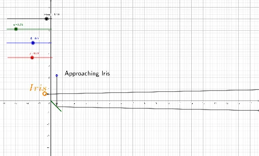
This example demonstrates the operation of an optical delay stage. Key mathematical concepts include functions, vectors, and transformations. Using GeoGebra commands such as Point, Intersect, and Line, the operation of the delay stage is dynamically illustrated. Suitable for high school physics and mathematics education.
GeoGebra Commands & Parameters
Point(xAxis) → CIntersect(xAxis, yAxis) → BLine(B, C) → fOrthogonalLine(A, f) → gIntersect(f, g) → DRotate(D, (-γ), A) → D'Angle(D', A, D) → αSegment(A, D') → hPoint(g) → ERotate(D, δ, E) → D'_1Angle(D, E, D'_1) → βSegment(E, D'_1) → iPoint(yAxis) → FRotate(F, ε, B) → F'Angle(F, B, F') → ζSegment(B, F') → jLine(G, g) → kIntersect(k, j) → HMirror(G, j) → G'Ray(G', H) → lIntersect(h, l) → IMirror(G', h) → G''Mirror(G', h) → G''_1Ray(G''_1, I) → mIntersect(i, m) → JMirror(G''_1, j) → KMirror(G''_1, i) → LRay(L, J) → nVector(H, I) → uVector(I, J) → vVector(G, H) → aPoint(xAxis) → OLine(O, a) → qIntersect(q, n) → MVector(J, M) → w
AI Drawing Prompt Reference
Draw an optical delay stage simulation. Start by creating point C on the x-axis, then create point B at the intersection of the x-axis and y-axis, and create line f through B and C. Next, create the perpendicular line g to f and create point D at the intersection of f and g. Rotate D around A counterclockwise by γ to get D', and calculate the angle α between D' and A. Then, create line segment h from A to D'. Create point E on g, rotate E around D clockwise by δ to get D'_1, and calculate the angle β between E and D', then create line segment i from E to D'_1. Create point F on the y-axis, rotate F around B clockwise by ε to get F', and calculate the angle ζ between F and B, then create line segment j from B to F'. Create line k through G and g, and calculate the intersection H of k and j. Then, mirror G about j to get G', create the ray l from G' through j, calculate the intersection I of h and l, mirror G' about h to get G'', create the ray m from G'' through j, calculate the intersection J of i and m, mirror G'' about j to get K, create the ray n from K through i, and calculate the intersection M of J and n, finally create vector w from J to M.
The prompt above was compiled from the original drawing commands and is for reference only.