
Lever Principle Demonstration
Loading the math board and drawing, please wait…
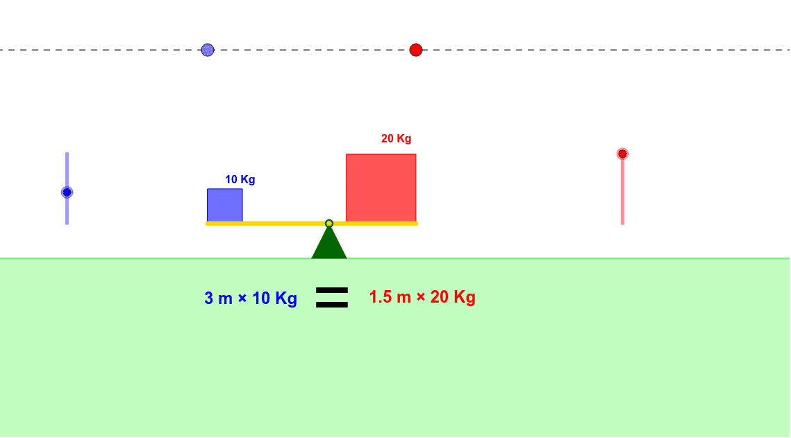
This example dynamically demonstrates the principle of levers, visually showing the relationship between torque and fulcrum. It involves core mathematical concepts such as torque calculation, vector application, geometric transformations, and inequalities. Construction highlights include commands like Point, Intersect, Ray, OrthogonalLine, Circle, Segment, Midpoint, Angle, Distance, Polygon, If, Rotate, and objects like f_1, g, G, F, etc. Suitable for high school physics and mathematics education to understand mechanical principles and geometric construction methods.
GeoGebra Commands & Parameters
Point(g) → GPoint(g) → FIntersect(g, h) → DRay(D, G) → kPoint(k) → IOrthogonalLine(I, k) → mIntersect(m, f_1) → SIntersect(g, i) → ERay(E, F) → jPoint(j) → HOrthogonalLine(H, j) → l_1Intersect(l_1, f_1) → TIntersect(d, m) → KCircle(K, f) → qIntersect(d, l_1) → JCircle(J, e) → pSegment(J, K) → nIntersect(q, n, 1) → MMidpoint(M, K) → RIntersect(p, n, 1) → L_1Midpoint(J, L_1) → LAngle(A, T, S) → γAngle(A, S, T) → βDistance(R, A) → RADistance(L, A) → LAPolygon(A, B, C) → poly1, c, a, bPolygon(J, L_1, 4) → poly2, r_1, s, t, a_1, N, OPolygon(M, K, 4) → poly3, b_1, c_1, d_1, e_1, P, QIf(tt < 0, (-β), If[tt ≟ 0, 0*°, γ]) → αRotate(poly2, α, A) → poly2'Rotate(J, α, A) → J'Rotate(K, α, A) → K'Segment(J', K') → n'Rotate(poly3, α, A) → poly3'Segment(A, S) → g_1Segment(A, T) → h_1If(tt < -1, (-β), If[tt < 1, ((γ + β) / 2 * tt) + (γ - β) / 2, γ]) → θRotate(N, α, A) → N'Rotate(Q, α, A) → Q'Distance(L, A) → lDistance(R, A) → rIf(tt < 0, "<", If[tt ≟ 0, "=", ">"]) → text5
AI Drawing Prompt Reference
Draw a lever principle demonstration: a horizontal base line with a fixed fulcrum, two rays extending from the fulcrum, points on each ray with perpendiculars meeting a second fixed line to give projection points; circles centered at these projections intersect the segment joining them, and their midpoints mark the force‑arm ends. On each side of the fulcrum construct a square that rotates about the fulcrum by an angle defined piecewise from a control parameter; also show the two arm lengths, the included angles, and a dynamic inequality symbol (<, =, >) that changes with the parameter, illustrating torque balance and imbalance.
The prompt above was compiled from the original drawing commands and is for reference only.