
Columbus Division Sequence and Coordinate Visualization (CUEBA0086)
Loading the math board and drawing, please wait…
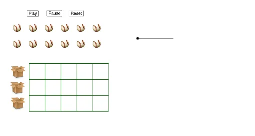
① This GeoGebra example demonstrates a division-based sequence themed around 'Columbus', integrating coordinate points, vector translations, and embedded images to visually connect sequence generation with geometric transformations. ② Core mathematical concepts include division operations, sequences and series, coordinate geometry, expected value, boxplots, and right triangle properties, highlighting the intersection of algebra and geometry. ③ Construction details: The Sequence command generates the sequence, Vector defines direction, If applies conditional logic, and Translate performs translations; objects include points A, B, C, D, etc., images pic1 to pic9, segments l1 to l8, vectors u, a, v, and transformed points C' and D', forming a multi-layered dynamic geometric structure. ④ Suitable for upper secondary to early university students, this example helps understand the combination of sequences and coordinate transformations, and serves as a comprehensive teaching tool for statistics and geometry.
GeoGebra Commands & Parameters
Sequence((3, k), k, 0, 6, 2) → l3Sequence((k, 0), k, 3, 13, 2) → l1Sequence((k, 6), k, 3, 13, 2) → l2Sequence((13, k), k, 0, 6, 2) → l4Sequence(Segment[Element[l1, k], Element[l2, k]], k, 1, 6) → l5Sequence(Segment[Element[l3, k], Element[l4, k]], k, 1, 6) → l6Sequence((k, 8), k, 1, 12, 2) → l7Sequence((k, 0.5), k, 3.5, 11.5, 2) → l8Vector(C, Element[l8, 1]) → uIf(0 ≤ a < 1, Vector[Dilate[u, a]], Vector[If[a ≥ 1, u]]) → vTranslate(C, v) → C'Translate(D, v) → D'Sequence((k, 2.5), k, 3.5, 11.5, 2) → l9Sequence((k, 4.5), k, 3.5, 11.5, 2) → l10Vector(I, Element[l9, 1]) → wIf(1 ≤ a < 2, Vector[Dilate[w, a - 1, I]], Vector[If[a ≥ 2, w]]) → bTranslate(I, b) → I'Translate(J, b) → J'Vector(K, Element[l10, 1]) → cIf(2 ≤ a < 3, Vector[Dilate[c, a - 2, K]], Vector[If[a ≥ 3, c]]) → dTranslate(K, d) → K'Translate(L, d) → L'Vector(M, Element[l8, 2]) → eIf(3 ≤ a < 4, Vector[Dilate[e, a - 3, M]], Vector[If[a ≥ 4, e]]) → fTranslate(M, f) → M'Translate(N, f) → N'Vector(O, Element[l9, 2]) → gIf(4 ≤ a < 5, Vector[Dilate[g, a - 4, O]], Vector[If[a ≥ 5, g]]) → hTranslate(O, h) → O'Translate(P, h) → P'Vector(Q, Element[l10, 2]) → iIf(5 ≤ a < 6, Vector[Dilate[i, a - 5, Q]], Vector[If[a ≥ 6, i]]) → jTranslate(Q, j) → Q'Translate(R, j) → R'Sequence((k, 10), k, 1, 12, 2) → l11Vector(K_1, Element[l8, 3]) → kIf(6 ≤ a < 7, Vector[Dilate[k, a - 6, K_1]], Vector[If[a ≥ 7, k]]) → lTranslate(K_1, l) → M_1Translate(L_1, l) → N_1Vector(I_1, Element[l9, 3]) → mIf(7 ≤ a < 8, Vector[Dilate[m, a - 7, I_1]], Vector[If[a ≥ 8, m]]) → nTranslate(I_1, n) → O_1Translate(J_1, n) → P_1Vector(G_1, Element[l10, 3]) → pIf(8 ≤ a < 9, Vector[Dilate[p, a - 8, G_1]], Vector[If[a ≥ 9, p]]) → qTranslate(G_1, q) → Q_1Translate(H_1, q) → R_1Vector(E_1, Element[l8, 4]) → rIf(9 ≤ a < 10, Vector[Dilate[r, a - 9, E_1]], Vector[If[a ≥ 10, r]]) → sTranslate(E_1, s) → S_1Translate(F_1, s) → T_1Vector(C_1, Element[l9, 4]) → tIf(10 ≤ a < 11, Vector[Dilate[t, a - 10, C_1]], Vector[If[a ≥ 11, t]]) → u_1Translate(C_1, u_1) → U_1Translate(D_1, u_1) → V_1Vector(A_1, Element[l10, 4]) → v_1If(11 ≤ a < 12, Vector[Dilate[v_1, a - 11, A_1]], Vector[If[a ≥ 12, v_1]]) → w_1Translate(A_1, w_1) → W_1Translate(B_1, w_1) → Z_1
AI Drawing Prompt Reference
Create a geometric visualization based on a sequence, showing coordinate points and vector transformations. Start by generating several sets of sequence points and connecting them with line segments to form geometric structures. Then define vectors and apply scaling and conditional transformations, translating points along the vector directions to create new points. Finally, connect these points with lines of different colors and thicknesses to form a complex geometric pattern, illustrating the combination of sequences, coordinate geometry, and vector transformations.
The prompt above was compiled from the original drawing commands and is for reference only.