
Rigid Motions Example by Megan Milano
Loading the math board and drawing, please wait…
In collections
Sequence of Rigid Motions
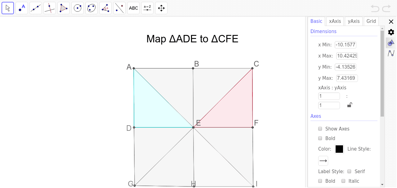
This example demonstrates the effects of rigid motions (translation, rotation) on geometric figures. It involves core concepts like transformation, geometric construction, and coordinate geometry. Constructed using commands like Point, Segment, Polygon. Suitable for high school mathematics teaching or geometric construction practice.
GeoGebra Commands & Parameters
Point(Circle[A, 4]) → BSegment(A, B) → aPoint(Circle[B, 4]) → CSegment(B, C) → bPoint(Circle[D, 4]) → ESegment(D, E) → cPoint(Circle[E, 4]) → FSegment(E, F) → dPoint(Circle[G, 4]) → HSegment(G, H) → ePoint(Circle[H, 4]) → ISegment(H, I) → fSegment(A, D) → gSegment(D, G) → hSegment(B, E) → iSegment(E, H) → jSegment(C, F) → kSegment(F, I) → lSegment(A, E) → mSegment(E, C) → nSegment(G, E) → pSegment(E, I) → qPolygon(E, B, C) → poly2, c_1, e_2, b_2Polygon(E, F, C) → poly3, c_2, e_3, f_1Polygon(E, I, F) → poly4, f_2, e_4, i_1Polygon(E, H, I) → poly5, i_2, e_5, h_1Polygon(E, G, H) → poly6, h_2, e_6, g_1Polygon(E, D, G) → poly7, g_2, e_7, d_1Polygon(E, D, A) → poly8, a_2, e_8, d_2Polygon(E, A, B) → poly1, b_1, e_1, a_1
AI Drawing Prompt Reference
Draw a geometric figure with multiple points connected by line segments to form several squares. Start by plotting a central point, then draw four circles centered at this point, marking points on the circumference and connecting them to form an outer square. Connect the vertices of this square back to the center to form inner segments. Finally, construct multiple squares using these points and segments, demonstrating the effects of rigid motion.
The prompt above was compiled from the original drawing commands and is for reference only.