
Orthographic Projection of a Cube
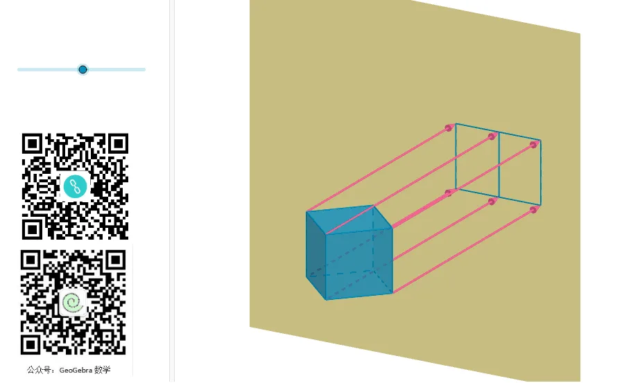
This example demonstrates the orthographic projection of a cube onto a specified plane. By constructing the eight vertices, twelve edges, and six faces of a cube using vector, plane, and rotation commands, it illustrates the geometric principles of orthogonally projecting a 3D solid along a specific direction onto a projection plane. Users can observe how the projected shapes of faces and edges change as the projection direction is varied, gaining insight into the relationship between spatial objects and their planar images. The applet visually clarifies the definition and fundamental properties of orthographic projection, including how parallel edges project to parallel or collinear segments, how the angles and relative sizes of faces are preserved or distorted depending on orientation, and how specific projection directions yield characteristic two-dimensional shapes such as squares, rectangles, or regular hexagons. Students can interactively manipulate the orientation of the cube and the angle of the projection plane, then immediately see the resulting changes in the projected figure. This hands-on exploration reinforces key spatial reasoning skills and deepens conceptual understanding of orthographic projection, a foundational topic in solid geometry and descriptive geometry. The interactive nature of the applet makes abstract geometric relationships tangible and accessible, supporting learners in building intuition for three-dimensional visualization and the mathematical rules that govern orthogonal mapping from space to a plane.
In collections
Solid Geometry
Loading the math board and drawing, please wait…